![<?echo $_SERVER['SERVER_NAME'];?>](/template/twentyseventeen/skin/images/header.jpg)
Exploration of steel barrel flanging machine (1)
Wuhan Metal Container Factory 2 Wang Lin
The burring machine is a machine used to complete the burring process of the steel barrel. It has a wide variety. If it is placed in the way of working the metal barrel, it can be divided into a horizontal flanger and a vertical flanger (where the horizontal placement of the barrel is called horizontal, and the vertical placement is called vertical); If it is classified by the number of edges that can be turned over, it can be divided into a single-head cuffing machine and a double-headed cuffing machine (one of which is only a single-headed cuffing machine at one end of the barrel); The points should be divided into rolling type cuffing machine and squeeze type cuffing machine; according to the processed barrel shape, it can be divided into a barrel cuffing machine and a special-shaped barrel cuffing machine. In the following, the main structure and working principle of the above various burring machines are described in two categories: the drum and the special-shaped bucket burring machine.
a drum cuffing machine
1. The main working parts of the rolling type rolling flange machine are two moving pressure rollers. The working principle is shown in Figure 1. During the work, the two rollers and the barrel body are moved relative to each other (rotation, translation or swing), so that the barrel can be turned over.

Figure 1 Rolling Flange Schematic
Drum rolling cuffing machines, although of many different configurations and types, must have two movements during the flanging process. First, the pressure roller should be fed relative to the barrel body so that the barrel edge can be turned outwards; the second is that the barrel body should be rotated around its axis so that the edge of the barrel can be turned over at the edge. There are two ways to get the rotary motion of the barrel: one is the active rotation of the barrel, and the other is the passive rotation of the barrel. The former is that the barrel body is directly driven by the motor and the speed reduction mechanism, and the rotating barrel body rotates the pressure roller by the frictional force when the flange is turned; the latter is driven by the motor and the speed reduction mechanism to drive the pressure roller to rotate, and the barrel body is frictional. The action is rotated by the actively rotating roller. The main structure and principle of the drum rolling flange machine are illustrated by examples.
Figure 2 is a diagram of the drive barrel of a horizontal double-headed flanging machine. The main working part of the machine is two actively rotating pressure rollers, so it is a rolling-type flanger for passive rotation. The structure of this machine is symmetrical. When working, both sides move at the same time, so that the sides of the barrel are turned at the same time. However, in order to express clearly, the upper right part of the figure is indicated as the highest position of the pressure roller, so that the barrel is fed and presented. The state to be flanged; the upper left half is the state in which the upper press roller is fed to the end position at the lowest position of the barrel. The following two movements of the rolling flange are used to illustrate the working principle and process of the flanger.
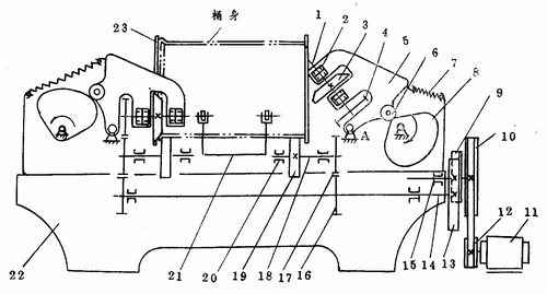
Figure 2 Drum double-head rolling flanger drive legend
1-upper roller shaft; 2-radial bearing; 3-upper roller; 4-gear; 5-pressure roller bracket; 6-roller; 7-spring; 8-cam; 9-gear; 10-belt pulley; - electric motor; 12-belt pulley; 13-gear; 14-spindle; 15- worm shaft; 16-gear; 17-gear; 18-lower roller; 19-lower roller; 20-bearing; Device; 22-frame; 23-baffle.
1) Feeding movement The feeding motion of the machine is realized by the upper pressing roller 3 swinging. The upper pressing roller 3 is fixed to the upper pressing roller shaft 1, and the upper pressing roller is supported by the roller holder 5 via the bearing 2. When the cam 8 rotates clockwise and the cam lift is continuously increased, the roller carrier 5 is oscillated counterclockwise around the fulcrum A by the roller 6. Then, the upper pressing roller 3 attached to the platen carrier is swung into the tub until the upper roller shaft 1 is in the horizontal position (shown in the upper left half of the figure), thereby completing the feeding. Then, the cam 8 is rotated to the minimum lift, and by the action of the spring 7, the press roller bracket 5 swings back to the original position clockwise, and the upper pressing roller 3 exits the outside of the tub, and the flanged body can be taken out at this time. The next bucket to be flanged can be placed.
The cam 8 is driven by an electric motor 11 which rotates the worm shaft 15 by a primary belt drive (pulleys 12 and 10). Since the worm wheel (not shown) engaged with the worm is coaxial with the cam 8, the worm shaft 15 The rotation causes the cam 8 to rotate slowly.
2) Main rotary motion The main rotary motion is expressed in the machine as the rotation of the upper and lower press rollers. This rotation is also driven by the motor 11. The motor 11 rotates the worm shaft 15, and since the gear 9 is fixed to the right end of the worm shaft 15, the main shaft 14 is rotated by the meshing with the gear. Further, the lower roller shaft 18 is rotated by the meshing of the gears 16 and 17, so that the lower pressing roller 19 fixed to the lower roller shaft obtains the main rotational motion. When the upper pressing roller is swung downwardly, the gears 4 and 17 are gradually engaged, so that the upper pressing roller also obtains the main rotational motion. At this time, the barrel between the upper and lower pressing rolls is subjected to the frictional force, and is driven by the pressing roller to rotate around its own axis, and at the same time, the burring is completed under the feeding action of the upper pressing roller.
During the flanging process, the baffle 23 functions to prevent the barrel from axially swaying, and the lower end of the baffle 23 must be opened to prevent the movement of the upper press roller.
The supporting and turning bucket device 21 supports the barrel body before the flange is turned, and is lifted and sent out from the barrel body. The working principle and basic structure are shown in Fig. 30. The bracket is curved in shape, and four rollers are mounted on the frame to support the horizontally placed barrel. When the piston in the cylinder is in the lowest position, the four bucket rollers support the barrel so that the barrel is in a state to be flanged. After the end of the flange is over, the piston pushes up the bucket rack. Make it swing up around its pivot point A, and the bucket body will be turned out of the bucket rack, then let the piston descend, the bucket rack will return, and the roller will support the next bucket.
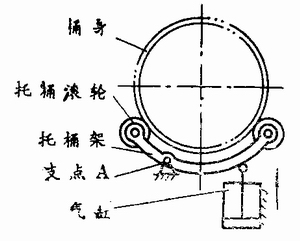
Figure 3 Schematic diagram of the tray and bucket device
The structure of the flanger shown in Fig. 2 is relatively simple and compact, and the double head is turned over at the same time, and the production efficiency is high, but the flanging uniformity is poor, and the flanging dimensional accuracy is low.
Figure 4 shows another form of a horizontal double-headed flanging machine. The machine is mainly composed of a bed body, a left and right headstock box, a left and right flanging pressing wheel, that is, an upper pressing roller, a left and right eccentric rolling plate, that is, a pressing roller, and a pneumatic device. The left and right structures of the device are identical and symmetrically arranged, so that the two sides of the barrel can be synchronously flanged. It can be combined with other equipment to form a production line for fully automatic production, or it can be semi-automatic production in a single process by manual upper and lower barrels. The following is a clue to the working principle of the cuffing machine and the single-step operation of the machine with the two movements of the barrel rolling type cuffing machine, namely the main rotary motion and the feeding movement of the extra bed head box. The working process.
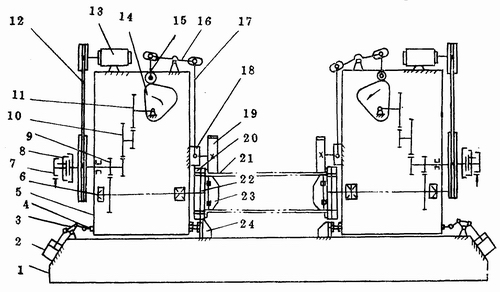
Figure 4 Schematic diagram of the transmission structure of the double-head rolling type flanger
1-bed; 2-cylinder; 3-three-eye plate; 4-spot; 5-head box; 6-spindle; 7-brake; 8-clutch; 9-gear; 1O-gear; 12-belt; 13-motor; 14-cam; 15-cam follower; 16-lever; 17-compressed rod; 18-slider; 19-flange pressure wheel; 20-adjusting disc; 21-barrel; 22-positioning plate; 23-eccentric rolling plate; 24-stroke limit block
1 The feeding movement of the headstock box firstly receives the power of the equipment, presses the left and right motor start button, presses the left and right fast forward buttons after the conveying device feeds, and the pistons in the left and right cylinders 2 go up through the three eye plates 3 and The horizontal tappet mechanism 4 feeds the left and right headstocks 1 and restricts the feeding process of the left and right headboards by the travel limit block 24, and the body 21 is now fitted over the eccentric rolling plate 23.
2 main rotary motion and feed motion press the left and right clutch upper buttons, the left and right clutches 8 are closed, and the power transmitted by the motor 13 via the primary belt drive 12 is rotated by the gear 9 to rotate the spindle 6; A cam 14 is rotated by the secondary gear transmissions 10, 11, and the cam is rotated by the cam follower rod 15 and the lever 16, the pressing rod 17, and the slider 18 to drive the flange pressing roller 19 fixed on the slider. The barrel body is pressed down, and the barrel body moves downward along with the eccentric rolling plate. At the same time, due to the frictional force, the barrel body and the cuffing pressing wheel rotate together with the eccentric rolling plate 23 to complete the cuffing. After the burring is finished, the burring pressure roller retreats, and the eccentric rolling plate and the barrel body move upwards with the lapped pressure roller due to the spring restoring force installed in the eccentric rolling plate until reset to the home position. Then, the left and right clutch release buttons are pressed, the left and right clutches 8 are disengaged, and the left and right brakes 7 brake the rotation of the first stage gear transmission shaft, so that the main shaft 6 and the flange side pressure roller 19 stop moving. Finally, press the left and right rewind buttons, the piston in the cylinder 2 goes down, and the left and right bed boxes return to the original position. The conveying device sends the barrel to the next process.
Compared with the swinging flanger structure of Fig. 2, the device is more reasonable, the adjustment is easier, the degree of automation is higher, the uniformity of the edge and the precision of the edge are also better, and the utility is widely used at present.
EFCOOKWARE is a professional manufacturer of Cast Iron Cookware. We have thousands of items can be provided, including dutch oven, casserole,baking pot,grill,skillet,pans,jambalaya pot,as well as potjies.
Cast iron cookware conducts and retains heat uniformly and for a very long time. The more you cook with cast iron, the better it gets as the oils and fats create a stick-resistant cooking surface while repelling the odors and tastes from previous dishes.This means each food item cooked in iron fry pans or other Cast Iron Pots has a pure flavor.
Iron is important for good health because it carries oxygen from the lungs, through the bloodstream, to the rest of the body.
Cast Iron Cookware
Pre-Seasoned Cast Iron Cookware, Wax Finish Cast Iron Cookware, Cast Iron Cookware Set, Enameled Cast Iron Cookware
Shijiazhuang Ever Fresh Trading Co., Ltd. , https://www.efhomedeco.com