![<?echo $_SERVER['SERVER_NAME'];?>](/template/twentyseventeen/skin/images/header.jpg)
Non-contact cards From the working frequency, non-card products can be divided into low frequency cards, high frequency cards, ultra high frequency cards and microwave cards. The non-contact TYPE A card is a high-frequency card that complies with the ISO14443 standard. Because it better balances functions, performance and cost, it is the first choice for non-contact technology in many domestic application industries. At present, it is mainly used in public transportation systems, highways and other project markets, as well as general markets such as access control, Internet cafes, campuses, parking lots, and membership cards. The annual market capacity exceeds 100 million and there is still a large growth potential.
Due to the promising market prospects of contactless cards, domestic and foreign manufacturers have introduced non-contact TYPE A cards. With its many years of development experience in non-receiving cards, Shanghai Huahong IC Co., Ltd. has carefully summarized the problems in chip design and application, and solved them one by one to provide customers with first-class products.
First, a brief introduction of non-connected TYPE A products
1 Typical application system
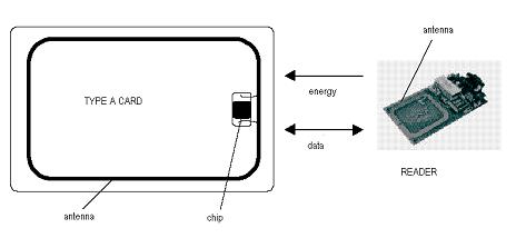
The picture above is a typical non-card application system. The chip is embedded in the module, and the external coil of 3 to 5 turns is used as an antenna, and the package is formed into a card to form a standard non-connected IC card. The card reader emits energy and data through a magnetic field. The card receives energy through antenna coupling and starts to work, and exchanges data with the card reader, thereby completing various applications.
2 Application process of non-connected TYPE A card
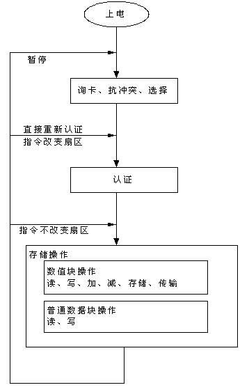
The typical application flow of a non-connected TYPE A card is shown in the figure above. After entering the field power-on, first check the card, and then complete the card selection through anti-collision. If there is only one card in the field strength, the process of anti-collision will be skipped and the card will be directly selected. After the card is selected, since the card also provides a security function, it is necessary to pass the triple authentication before the card can be read, written, added, subtracted, restored, paused, and the like.
3 circuit module diagram of non-connected TYPE A card chip
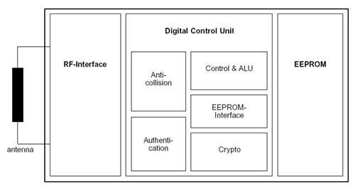
The entire non-contact chip can be divided into three modules: EEPROM for storing data; RF-interface external antenna for generating energy and data exchange; digital control part including anti-collision circuit, authentication circuit, encryption circuit and other control interfaces Circuit.
Second, the design optimization of non-connected TYPE A card chip
In recent years, various non-connected TYPE A card chips have emerged and gradually established high-quality domestic brands. However, there are still some problems in practical applications. Through customer feedback, investigation, sample testing and other analytical methods, we divide these problems into three categories: logic function, RF, and production yield. This section details the phenomena, causes, and solutions for these issues.
1 logic function problem
The errors in this part are relatively simple and can be divided into the following two categories:
1) Card deadlock
Card deadlocks occur more often when the player enters the field slowly. The card is prone to deadlock: the card reader will not respond correctly if it sends any commands. When such a problem occurs, the user must take the card out of the field and re-enter the field strength before the card can resume work.
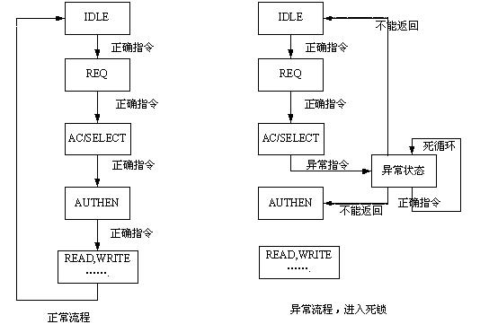
The root cause of this kind of problem is that when the chip is in a certain state, it suddenly receives an error or abnormal instruction, such as an instruction issued by an abnormal workflow. The state machine controlled by the internal logic of the chip stops somewhere and does not return correctly. When the corresponding state is reached, the normal command is received again, and the chip cannot make a correct judgment. The internal logic control state machine has been stopped somewhere, causing a deadlock. When the card is at the critical point of the working distance, it is easy to treat the received command as an abnormal command, or when the card returns the command correctly, the card reader fails to demodulate it, and the card reader thinks that the card has moved out of the field and will re- The card inquiry command is sent, but the card does not recognize the card instruction. At this point the card is in a deadlock state. For example, the following picture:
The solution is for various abnormal instructions or states. In the design of the chip state machine, it must be considered which state should be skipped, how to recover, and so on. If the logic circuit design of the chip only satisfies the normal function state flow, it is not enough, and various error conditions must be considered.
2) Instruction return timeout
This requires the chip to have time constraints on the processing of various instructions. Since the current application system is based on the existing non-card product, it sets the timeout and protection time for the card's return time. If the domestic chip returns too fast or too slow, it may cause communication errors. From the current situation, the problem of returning the instruction timeout is more prominent. The main reason is that the chip erases the EEPROM for too long.
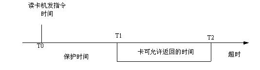
As can be seen from the above figure, the card should return during T1~T2, and returning at other times may be judged by the card reader.
The solution is to investigate the timeout and protection time set by the reader to determine the design metrics. Normally, the protection time is very short, so the real solution is to increase the processing speed of the chip as much as possible, especially to reduce the erasing time of the EEPROM, and the card returns as soon as possible to avoid the problem of timeout.
2 RF RF issues
1) The chip has poor adaptability to different antennas
This mainly means that when the chip is matched with different types of antennas, the minimum working field strength is different. The intuitive performance is that for the same card reader, the non-contact cards with different antennas have different working distances. At present, the antennas used by domestic card factories are basically wound by hand, and the consistency of the antennas cannot be controlled. Therefore, even if the cards produced in the same batch are used, some work distances are relatively long, and some work distances are relatively close.
Different types of antennas have different inductances, capacitances, and resistances. After the chip is formed into a non-connected card, the cards have different resonant frequencies. When the resonant frequency of the card is consistent with the operating frequency of the card reader system, the amplitude of the resonance is the largest, the energy coupled to the card is the most, and the distance the card can work is farther. So in theory, cards with different antennas will have different working distances. However, when the chips of international advanced manufacturers match different antennas, the difference of working distance is not large. When the domestic non-contact chips use different antennas, the working distance is significantly different. Even under some antennas, the working distance is too short to be normal. application.
Bedroom Nightstands,Bedside Cabinets,Modern Nightstands,Bedroom End Tables
Jiangxi Yingkai Wood Products Co., Ltd. , https://www.anjufurniture.com