![<?echo $_SERVER['SERVER_NAME'];?>](/template/twentyseventeen/skin/images/header.jpg)
Exploration of metal barrel burring machine (1)
The burring machine is a machine for completing the metal barrel burring process. If it is placed in the way of working, the metal bucket can be divided into a horizontal flanger and a vertical flanger (where the horizontal placement of the bucket is called horizontal, and the vertical placement is called vertical); According to the number of sides that can be turned over, it can be divided into a single-head cuffing machine and a double-headed cuffing machine (one of which is a single-headed cuffing machine that only flies one end of the barrel at a time, and both ends of the barrel are flanged at the same time. The so-called double-head flanging machine); in terms of the principle of flanging, it should be divided into hydraulic flanging machine and squeeze-type flanging machine; according to the processed barrel shape, it can be divided into drums Flanging machine and shaped bucket burring machine. In the following, the main structure and working principle of the above various burring machines are described in two categories: the drum and the special-shaped bucket burring machine.
First, the barrel flanger
1. Wave pressure type: The main working parts of the rolling type flanger are two moving pressure rollers. The working principle is shown in Figure 1. During work, the two pressure sticks and the barrel body are moved relative to each other (rotate, translate or swing), so that the barrel can be turned over.
Although the drum rolling type flanger has many different structures and types, it must have two kinds of movements during the burring process. First, the pressure roller should be fed with respect to the barrel body so that the barrel side can be outward. Turning out; the second is that the barrel should be rotated around its axis so that the edge of the barrel can be turned over at the edge. There are two ways to get the rotary motion of the barrel body. One is the barrel body for active rotation, and the other is the barrel body for passive rotation. The former is that the barrel body is directly driven by the motor and the speed reduction mechanism. When the flange is turned, the rotating barrel rotates by the friction force; the latter is driven by the motor and the speed reduction mechanism, and the barrel body is frictional. The action is rotated by the active rotation. The main structure and principle of the drum rolling flange machine are illustrated by examples.
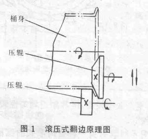
Figure 2 is a transmission diagram of a horizontal double-headed flanging machine. The main working part of the machine is two actively rotating pressure rollers, so it is a rolling-type flanger for passive rotation. The structure of this machine is symmetrical. When working, both sides move at the same time, so that the sides of the barrel are flanging at the same time. However, in order to express clearly, the upper and lower parts of the figure are expressed as the upper part of the upper press, so that the barrel is fed. The state to be cuffed; the upper left half is the state in which the upper press is fed to the end of the barrel at the lowest position. The following two movements of hydraulic flanges are used to illustrate the working principle and process of this plane.
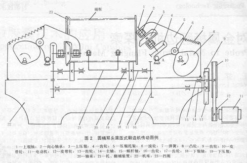
1) Feeding movement: The feeding motion of the machine is realized by the upper pressing roller 3 swinging. The upper pressing roller 3 is fixed to the upper pressing roller shaft 1, and the upper pressing roller shaft 1 is supported by the roller holder 5 through the bearing 2. When the cam 8 rotates clockwise and the cam lift is continuously increased, the press holder 5 is oscillated counterclockwise around the fulcrum A by the roller 6. Then, the upper press 3 mounted on the roller carrier is swung into the tub until the upper roller shaft 1 is in the horizontal position (shown in the upper left half of the figure), thereby completing the feed. Then, the cam 8 is rotated to the minimum lift, and by the action of the spring 7, the press roller bracket 5 swings back to the original position clockwise, and the upper pressing roller 3 exits the outside of the tub, and the flanged frame can be taken out at this time. The next bucket to be flanged can be placed.
The cam 8 is driven by an electric motor 11 which rotates the worm shaft 15 by a primary belt drive (pulleys 12 and 10). Since the worm wheel (not shown) engaged with the worm is coaxial with the cam 8, the worm shaft 15 The rotation causes the cam 8 to rotate slowly.
2) Main rotary motion: The main rotary motion is expressed in the machine as the rotation of the upper, lower, and pressure rollers, and this rotation is also driven by the motor 11. The motor 11 rotates the worm shaft 15, and since the yoke 9 is fixed to the right end of the worm shaft 15, the main shaft 14 is rotated by the engagement with the gear 13. Further, by the meshing of the gears 16 and 17, the lower shaft 18 is rotated, and thus the lower pressing roller 19 fixed to the lower roller shaft obtains the main rotational motion. When the upper pressing roller is swung downwardly, the gears 4 and 17 are gradually engaged, so that the upper pressing roller also obtains the main rotational motion. At this time, the barrel between the upper and lower pressing rolls is subjected to the frictional force, and is driven by the pressing roller to rotate around its own axis, and at the same time, the burring is completed under the feeding action of the upper pressing roller.
During the flanging process, the retaining ring 23 acts to prevent the barrel from axially swaying, and the lower end of the retaining ring 23 must be opened to prevent the movement of the upper press.
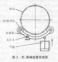
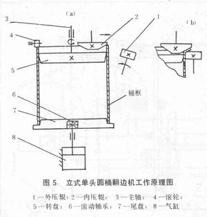
The supporting and turning bucket device 21 plays the role of supporting the tub frame before the flanging, and functions as a lifting frame after the flanging. Its working principle and basic structure are shown in Figure 3. In the figure, the bucket frame is curved, and four rollers are mounted on the frame to support the horizontally placed barrel frame. When the piston in the cylinder is in the lowest position, the four bucket cylinders hold the bucket frame, so that the bucket frame is in a state to be flanged. After the end of the flange is over, the piston pushes up the bucket rack. Make it swing up around its pivot point A, and the bucket frame is turned out of the bucket rack. Then let the piston down, hold the bucket back, and the roller will hold the next bucket.
The structure of the flanger shown in Fig. 2 is relatively simple and compact, and the double head is turned over at the same time, and the production efficiency is high, but the flanging uniformity is poor, and the flanging dimensional accuracy is low.
Figure 4 shows another form of a horizontal double-headed flanging machine. The machine is mainly composed of a bed body, a left and right headstock box, a left and right flanging pressing wheel, that is, an upper pressing roller, a left and right eccentric rolling plate, that is, a pressing roller, and a pneumatic device. The left and right structures of the device are identical and symmetrically arranged, so that the two sides of the barrel can be synchronously flanged. It can be combined with other equipment to form a production line for fully automatic production, or it can be semi-automatic production in a single process by manual upper and lower barrels. In the following, the two movements of the drum rolling type cuffing machine, namely the main rotary motion and the feeding movement of the extra bed head box outside the feed movement, are used as clues to explain the working principle of the special plane and the single-step operation of the machine. process.
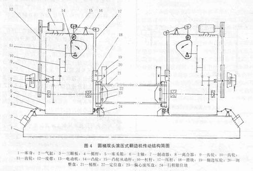
a. Feeding movement of the headboard: First, the equipment is connected to electricity, press the left and right motor start button, press the left and right fast forward buttons after the feeding device is fed, and the pistons in the left and right cylinders 2 go up, pass three The eye plate 3 and the horizontal tappet mechanism 4 feed the left and right headstocks 1 , and the stroke limit block 24 restricts the delivery process of the left and right headboards, and the barrel body, that is, the bucket frame 21 is set in the eccentric roll. Press on the platen 23.
b. Main rotary motion and feed motion Press the left and right clutches to close the button, and the left and right clutches 8 are closed. At this time, the power transmitted by the motor 13 via the primary belt drive 12 is passed through the gear transmission 9 to make the spindle 6 rotation; the other rotates the cam 14 through the two-stage gear transmissions 10, 11, and the rotation of the cam is further driven by the cam follower rod 15 and the lever 16, the pressing rod 17, and the slider 18 to be flanged on the slider. The pressure roller 19 presses down the bucket frame, and the bucket frame moves downward together with the eccentric hydraulic disk. At the same time, due to the frictional force, the bucket frame and the flanged pressure roller rotate together with the eccentric hydraulic disk 23 to complete the flange. After the burring is finished, the burring pressure roller retreats, and the eccentric hydraulic disc and the barrel frame move upward with the burring pressure roller due to the spring restoring force installed in the eccentric hydraulic disk until reset to the home position. Then, the left and right clutch release buttons are pressed, the left and right clutches 8 are disengaged, and the left and right brakes 7 brake the rotation of the first stage gear transmission shaft, so that the main shaft 6 and the flange side pressure roller 19 stop moving. Finally, press the left and right rewind buttons, the piston in the cylinder 2 goes down, and the left and right bed boxes return to the original position. The conveying device sends the barrel frame to the next process.
Compared with the swinging flanger structure of Fig. 2, the device is more reasonable, the adjustment is easier, the degree of automation is higher, the uniformity of the edge and the precision of the edge are also better, and the utility is widely used at present.
When you need a bag to packing your Jewelry Box, you can buy the Gift Bag by the way. There are various shape and material gift bags for choice, you can choose the suitable one for yourself. Meanwhile, you can take the gift bag as a shopping bag, You can use different shopping bags to match your outfit. That will make you feel different everyday!
Brand Name: Jinao
Place of Origin: Guangdong, China(mainland)
Surface Material: Customized
Color: Customized
Size: Multi-size + Customized
Feature: wholesale
Logo Printing: Customized
Usage: Gift Bag / shopping bag
Gift Bag
Gift Bag,Shopping Gift Bag,Gift Bag For Shopping Bag,Gift Bag For Kids
DongGuan Jinao Packaging Products Co., Ltd , https://www.jinaojewelrybox.com